1. Polarization Properties of Light
Light is an electromagnetic wave consisting of oscillating electric and magnetic fields perpendicular to each other and to the direction of propagation. The polarization properties of light describe the orientation of these electric field oscillations.
In unpolarized light, such as that emitted by the sun or incandescent bulbs, the electric field oscillates in all possible directions perpendicular to the propagation axis. This random orientation is what makes most natural light unpolarized—light that requires specific processing for technologies like liquid crystal display (LCD). For LCDs to function, this unpolarized light must pass through a polarizing filter to align its electric field in a single direction, a step that enables liquid crystals to modulate light and produce displayable content.
Polarized light, by contrast, has its electric field oscillations confined to a specific plane. This phenomenon finds extensive application in various technologies, most notably in the lcd screen technology that powers our smartphones, televisions, and computer monitors.
The polarization of light can occur through several mechanisms: reflection, refraction, scattering, and absorption. For example, light reflecting off water or glass surfaces becomes partially polarized, a property utilized in polarizing sunglasses to reduce glare. This same principle is employed in the lcd screen to control the amount of light passing through each pixel.
Understanding polarization is crucial because it reveals important information about the interaction between light and matter. When light interacts with certain materials, its polarization state can change, providing insights into the material's structure and properties. This principle is fundamental to how an lcd screen operates, where liquid crystal molecules rotate the polarization of light to create images.
In nature, polarization phenomena are widespread. For instance, the sky appears polarized due to Rayleigh scattering, which helps bees and other insects navigate. This natural polarization is analogous to the controlled polarization used in technology, including the lcd screen that has become integral to modern life.
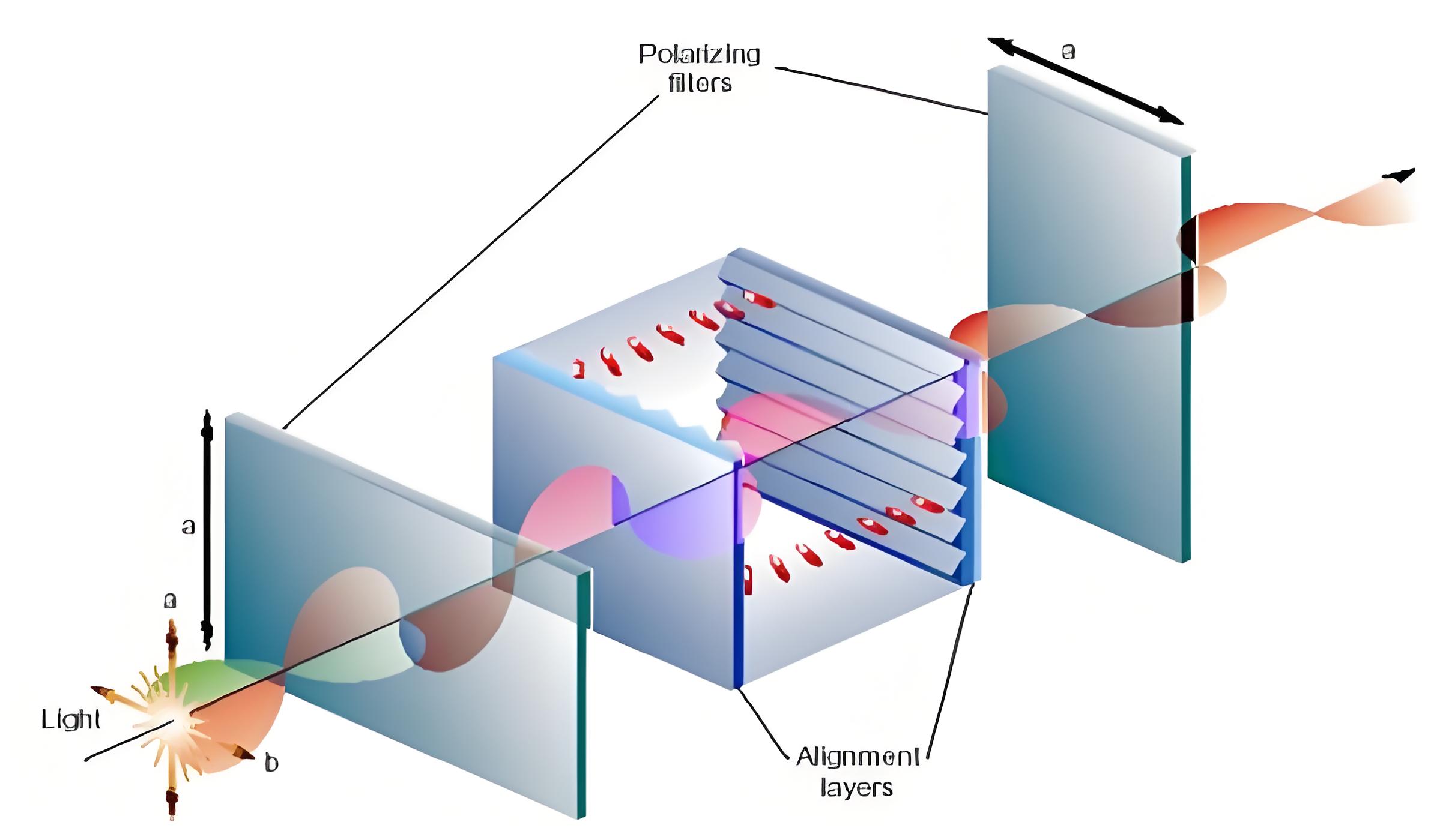
Natural light becomes polarized after passing through a polarizing filter
Linear Polarization
Electric field oscillates in a single plane
Circular Polarization
Electric field rotates in a circular motion
Elliptical Polarization
General case of polarization with elliptical trajectory
Unpolarized
Random orientation of electric field vectors
Polarization Demonstration
Rotate the polarizer to see how it affects the transmitted light intensity:
2. Representation Methods of Light Polarization States
Several mathematical formalisms exist to describe the polarization states of light, each offering unique advantages depending on the application context. These representations allow scientists and engineers to precisely calculate and predict how polarization changes when light interacts with various materials— a capability critical for optimizing technologies like liquid crystal display (LCD), where even tiny deviations in polarization control can affect display clarity and color accuracy.
The Jones vector formalism, developed by R.C. Jones, represents polarized light as a two-element complex vector describing the amplitude and phase of the electric field components along two orthogonal directions. This method is particularly useful for describing the behavior of polarized light in optical systems, including the complex manipulation of light within an lcd screen.
For partially polarized light, the Stokes vector (or Stokes parameters) provides a more appropriate description using four real numbers that quantify the polarization properties. This approach is widely used in experimental settings due to its direct measurability. Modern lcd screen technology relies on precise control of these Stokes parameters to achieve accurate color reproduction and brightness levels.
The Poincaré sphere offers a geometric representation where each polarization state corresponds to a unique point on the surface of a unit sphere. This visualization tool helps in understanding transitions between different polarization states, making it invaluable in the design and analysis of polarization-sensitive systems like the lcd screen.
Mueller matrices extend these concepts by describing how an optical element transforms the polarization state of light. A Mueller matrix has 16 elements that completely characterize the polarization-altering properties of a device or material. In lcd screen manufacturing, precise measurement and control of these matrices ensure consistent performance across millions of pixels.
Each representation method has its domain of applicability. Jones vectors are most efficient for fully polarized light in coherent systems, while Stokes vectors and Mueller matrices handle partially polarized light and incoherent systems. Understanding these representations is essential for designing advanced optical systems, including the sophisticated polarization control mechanisms in modern lcd screen technology.
Polarization State Representations
Different mathematical formalisms for describing polarization
Jones Vector Examples
Linear horizontal: [1, 0]T
Linear vertical: [0, 1]T
Linear 45°: (1/√2)[1, 1]T
Right circular: (1/√2)[1, -i]T
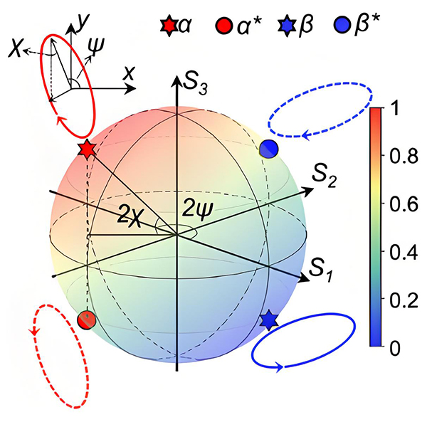
Poincaré sphere representation of polarization states
Stokes Parameters
- S₀: Total intensity of the light beam
- S₁: Difference between horizontal and vertical linear polarization
- S₂: Difference between 45° and 135° linear polarization
- S₃: Difference between right and left circular polarization
Stokes Parameters in LCD Technology
The following chart illustrates typical Stokes parameter values measured across different regions of an lcd screen:
3. Polarization of Light Propagation in Anisotropic Media
Anisotropic media exhibit optical properties that vary with direction, profoundly affecting the polarization of light as it propagates through them—a phenomenon critical to technologies like the display screen. Unlike isotropic materials such as glass or water, which have the same optical properties in all directions, anisotropic materials like calcite or liquid crystals have different refractive indices depending on the direction of light propagation and polarization. In display screens (particularly liquid crystal displays), this directional variation in optical properties is harnessed to control light transmission pixel by pixel, forming visible images through precise manipulation of polarized light.
When light enters an anisotropic medium, it generally splits into two orthogonally polarized waves traveling at different velocities—this phenomenon is known as double refraction or birefringence. These two waves, often called the ordinary and extraordinary rays, experience different refractive indices and may follow different paths through the material. This fundamental principle is exploited in the lcd screen, where liquid crystal molecules act as controllable anisotropic media.
The optical behavior of anisotropic materials is described using the dielectric tensor, a mathematical construct that relates the electric displacement vector to the electric field vector in three dimensions. The eigenvectors of this tensor correspond to the directions of linear polarization for which the wave propagates without changing its polarization state. This complex interaction forms the basis of how lcd screen technology manipulates light to create images with varying brightness and color.
Liquid crystals, the key material in lcd screen technology, exhibit anisotropic properties that can be controlled by an applied electric field. In their natural state, liquid crystal molecules align in a way that makes them birefringent. When an electric field is applied, the molecules reorient, changing their birefringent properties. This controllable anisotropy allows precise manipulation of light polarization, enabling the formation of images on the display.
The study of light propagation in anisotropic media also involves concepts like optical axis, Fresnel equations for anisotropic materials, and polarization mode dispersion. These phenomena are critical considerations in optical communication systems, polarimetry, and display technologies. Understanding how anisotropic materials affect light polarization has been instrumental in the development of modern lcd screen technology, which relies on precise control of these optical effects to produce high-quality images.
Applications of anisotropic optical phenomena extend beyond displays. They include stress analysis using photoelasticity, optical isolators in laser systems, and polarization microscopy. Each of these applications leverages the unique way anisotropic materials interact with polarized light, much like the controlled interaction that occurs within every lcd screen to produce the visual information we rely on daily.
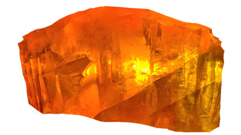
Double refraction in calcite crystal demonstrating anisotropic light propagation
Birefringence in LCD Technology
Liquid Crystal Alignment
In an lcd screen, liquid crystal molecules align in specific configurations to control light polarization:
- Twisted nematic (TN) alignment for basic displays
- In-plane switching (IPS) for wider viewing angles
- Vertical alignment (VA) for higher contrast ratios
Refractive Index Ellipsoid
An important concept in anisotropic optics, representing the variation of refractive index with direction and polarization.
Liquid Crystal Behavior in LCD Screens
Adjust the applied voltage to see how liquid crystal molecules reorient, changing the polarization properties in an lcd screen:
Polarization Effect
As voltage increases, liquid crystal molecules align with the electric field, reducing their ability to rotate light polarization. This controlled rotation is what creates the pixels in an lcd screen.
0V
Maximum Rotation
5V
Minimum Rotation
4. Phase Plates
Phase plates (also known as retarders) are optical devices that introduce a controlled phase difference between orthogonal components of polarized light, critical for lcd display screen. This phase difference can transform one polarization state into another, making phase plates essential components in many optical systems, including the sophisticated optics of an lcd screen.
A phase plate typically consists of a birefringent material with a specific thickness, designed to introduce a precise phase shift between the ordinary and extraordinary rays. The magnitude of this phase shift depends on the material's birefringence and the thickness of the plate, following the relationship: Δφ = (2π/λ)·d·(nₑ - nₒ), where d is the thickness, and nₑ and nₒ are the extraordinary and ordinary refractive indices, respectively.
In lcd screen technology, phase plates play a critical role in controlling the polarization state of light as it passes through the display. They help compensate for phase differences introduced by other components, ensuring that the light emerging from each pixel has the correct polarization state to interact properly with the analyzer, resulting in accurate brightness control.
Common types of phase plates include quarter-wave plates, half-wave plates, and full-wave plates, classified by the phase difference they introduce (π/2, π, and 2π radians, respectively). A quarter-wave plate can convert linearly polarized light to circularly polarized light and vice versa, while a half-wave plate rotates the polarization direction of linearly polarized light by twice the angle between the plate's optical axis and the incident polarization direction.
Modern manufacturing techniques allow for the production of very precise phase plates with minimal wavelength dependence, making them suitable for broadband applications. In lcd screen production, these precision components are carefully aligned to ensure uniform performance across the entire display area, contributing to consistent image quality and color reproduction.
Phase plates find applications beyond display technology, including in polarization microscopy, ellipsometry, and optical communication systems. They are essential for manipulating and analyzing polarization states in scientific research and industrial applications. The principles behind phase plates are fundamental to understanding how an lcd screen works, as they form part of the optical stack that converts electrical signals into visible light patterns.
The development of advanced phase plate technologies, such as liquid crystal retarders, has enabled dynamic control of phase differences using applied electric fields. These adjustable phase plates are used in adaptive optics systems and have also contributed to the evolution of lcd screen technology, allowing for more precise control over individual pixels and improved display performance.
Types of Phase Plates
Quarter-Wave Plate
Introduces a 90° (π/2) phase shift, converting between linear and circular polarization. Essential in lcd screen backlighting systems.
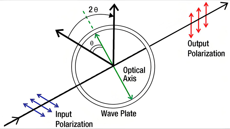
Half-Wave Plate
Introduces a 180° (π) phase shift, rotating the plane of linearly polarized light. Used in lcd screen color filters.
Phase Plate Applications in LCD Technology
- Compensating for color shifts in lcd screen displays
- Improving viewing angle performance
- Enhancing contrast ratios by controlling polarization states
- Correcting phase errors introduced by liquid crystal layers
Phase Plate Effect on Polarization
The following visualization shows how different phase plates transform the polarization state of light, a principle essential to lcd screen operation:
Input: Linear Polarization
Electric field oscillates in vertical plane
Phase Plate
Introduces controlled phase shift
Output: Transformed Polarization
Right circular polarization
5. Wave Plates
Wave plates are specialized optical components that manipulate the polarization state of light by introducing a precise phase difference between orthogonal polarization components, integral to devices like lcd monitors. Unlike simple phase plates, wave plates are designed to work over specific wavelength ranges and find extensive application in precision optical systems, including the high-performance lcd screen displays used in professional monitors and high-definition televisions.
The operation of a wave plate relies on birefringence—the property of certain materials to exhibit different refractive indices for light polarized in different directions. By carefully selecting the thickness and orientation of the birefringent material, wave plates can introduce a controlled phase shift between the ordinary and extraordinary waves. This phase manipulation is crucial for achieving accurate color reproduction and grayscale performance in modern lcd screen technology.
Achromatic wave plates are engineered to provide a consistent phase shift over a broad range of wavelengths, making them essential for full-color lcd screen displays that must handle red, green, and blue light equally well. These sophisticated components combine multiple birefringent materials with different dispersion properties to minimize wavelength dependence, ensuring uniform polarization manipulation across the visible spectrum.
In lcd screen construction, wave plates are strategically placed within the optical stack to optimize performance. They often work in conjunction with polarizers and liquid crystal layers to control the amount of light passing through each pixel. By precisely adjusting the phase relationship between polarization components, wave plates enhance contrast ratios, reduce color shifts at different viewing angles, and improve overall image quality.
The manufacturing process for high-quality wave plates demands exceptional precision. The birefringent materials must be cut and polished to exact thicknesses, often with tolerances measured in nanometers. The optical axis must be aligned with extreme accuracy to ensure the desired phase shift. These stringent manufacturing requirements contribute to the superior performance of premium lcd screen displays compared to their lower-cost counterparts.
Beyond display technology, wave plates are used in a wide range of applications, including laser systems, spectroscopy, and optical metrology. They enable precise control of polarization states for scientific research and industrial processes. The same principles that make wave plates indispensable in these advanced applications also make them critical components in the continued evolution of lcd screen technology, as manufacturers strive for higher resolutions, better color accuracy, and improved energy efficiency.
Recent advancements in wave plate technology, such as the development of thin-film and liquid crystal wave plates, have expanded their application in flexible displays and adaptive optical systems. These innovations are helping to push the boundaries of what's possible with lcd screen technology, enabling new form factors and performance capabilities that were previously unattainable.Electronic shelf labels.
Wave Plate Technology
Achromatic Wave Plates
Provide consistent phase shifts across multiple wavelengths, essential for full-color lcd screen displays.
Zero-Order Wave Plates
Thin design with minimal wavelength dependence, ideal for high-resolution lcd screen applications.
Multiple-Order Wave Plates
Thicker construction providing larger phase shifts, used in specialized lcd screen components.
Wave Plate Performance in LCD Screens
Key Specifications
Phase Tolerance
±λ/100 to ±λ/10
Wavelength Range
400-700 nm (visible)
Temperature Stability
0.001λ/°C typical
Damage Threshold
10-100 W/cm²
Wave Plates in LCD Screen Construction
The following diagram illustrates the position and function of wave plates within a typical lcd screen optical stack:
White LED or CCFL illumination
Converts to linear polarization
Controls phase relationship
Electrically controlled birefringence
Red, green, and blue subpixels
Second polarizer orthogonal to first