コンテンツへスキップ
TOP
店舗一覧
ごっつい池袋
ごっつい新橋
ごっつい笹塚
ごっつい蒲田
ごっつい祖師ヶ谷
ごっつい下高井戸
ごっつい大泉
ごっつい経堂
ごっつい祐天寺
MENU
店内メニュー
テイクアウトメニュー
SNS
Twitter
Instagram
Facebook
お問い合わせ
検索:
TOP
店舗一覧
ごっつい池袋
ごっつい新橋
ごっつい笹塚
ごっつい蒲田
ごっつい祖師ヶ谷
ごっつい下高井戸
ごっつい大泉
ごっつい経堂
ごっつい祐天寺
MENU
店内メニュー
テイクアウトメニュー
SNS
Twitter
Instagram
Facebook
お問い合わせ
検索:
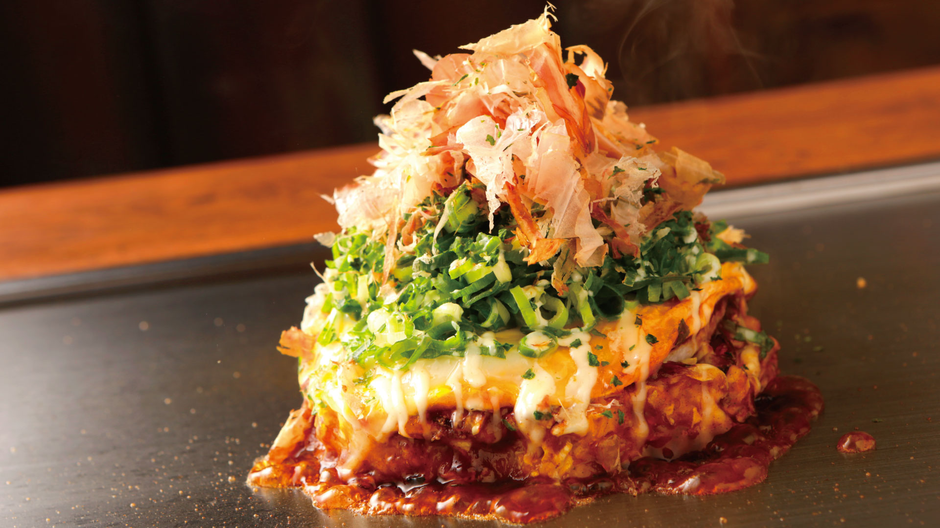
はじまりは、
「東京には美味しいお好み焼がない」
というシンプルな思いでした。
あれから30年。
味を守り続けながら、進化し続けてきた“ごっつい”
笑顔があふれ、元気になれる空間が、ここにあります。
ごっついメニュー
テイクアウトメニュー
gottsui.521
【ごっつい新橋】 店内の木札一新✨
【ごっつい蒲田】 8月27日で閉店です
【ごっつい蒲田】 店長ひかりちゃん
【ごっつい新橋】 新橋、中野オーナ
【ごっつい】 ごっついをこよなく愛
さらに読み込む...
Instagram でフォロー